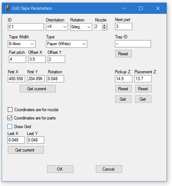
The Edit Tape Parameters dialog comes up when you click “Add” on the Tape Positions page or right click on an existing tape and select Edit from the menu:
The “ID” column is the name for this tape; you can use any name you want. The important thing is to use a name that you can identify later.
“Orientation” tells the machine which direction the part count increases. Please see this page for orientation illustrations.
“Part Rotation” tells which way the components are placed on the tape pockets. A tape in +Y orientation with part rotation value of 0 means that components from that tape will be placed to the PCB “as is”. If part rotation is 90 degrees, components are rotated 90 degrees counterclockwise (positive direction) and so on. Rotation in CAD datais added to this when the part is placed. The different tape orientations are automatically accounted for.
“Nozzle” is the default nozzle number for this part. This can be changed on the job dialog.
“Next part” is the number of the part used next. As defined, the tape parameters refer to part tapes with part numbers starting from 1. The tape can be partly used, so here you tell the software where to start picking.
“Tape Width” dropdown column has the standard tape width and component pitch selections. The first number is the tape width, the second number is component pitch. Selecting a standard width automatically updates the pitch and offset values correctly.
“Type” dropdown determines the video processing used to locate the tape holes.
As noted, the “Part Pitch”, “Offset X” and “Offset Y” values are automatically filled with correct values for standard tapes. If you select “custom” from the “Tape Width” dropdown, you can set in non-standard values here. (For example, setting Pitch to 0 makes the software to pick up the part from the same location each time.)
“Tray ID” sets the Tray ID of the tape. On the main Tape positions page, you can save and load several tape definitions at the time. The idea is that you can use trays of tapes (most likely, on holders) mounted on a tray with alingment aids (so that they sit on the same location each time) and this way, replace several tapes together. “Reset” button removes the Tray ID.
“First X” and “First Y” set the location of the first hole (or part, see below). The “Get Current” button fills the boxes with the current machine location.
“Coordinates are for parts” checkbox omits the hole recognition. Instead, the software uses the given locations directly. Checking the box enables the “Last X” and “Last Y” boxes, where you set the location of the last part on the tape. Please note, that it doesn’t actually need to be the last (at least until capacity info is added to the software), just a part somewhere further away is sufficient. When you use the coordinates directly, the rotation value on the upper row doesn’t apply anymore. Instead, you set the value in the “Rotation” box by the First X, First Y boxes. This value is “direct”. For example, if you set -90 here, the part will be rotated -90 degrees (clockwise) when placed, if the CAD data says 0. “Draw grid” puts an alignment help grid to help in rotation. If you have enabled mouse wheel rotation, you can do that, and the grid will rotate accordingly.
“Coordinates are for nozzle” makes the pickup use the given location without moving the machine. Other operations use the location shown on camera image and move the nozzle there. Checking this omits the move. You would use this for feeders: Check “Coordinates are for parts” to omit optical recognition. Jog the nozzle to the feeder pickup position, click “get current” to get the first X,Y position, click “Get” for pickup Z and finally, set part pitch to 0 to make the pickup happen from the same spot every time.
The “Get current” button under the last X, last Y boxes takes the current position of the machine and places that to the boxes. Do note, that while this dialog stays topmost in the program, you can activate the main window under it, jog the machine to the right position and click the button.
The “Pickup Z” and “Placement Z” values are the Z values used for the respective operations. With the buttons, you can “Reset” the values, causing the machine to measure them when used. Again, the “Get” button takes the current machine position to the corresponding box.