If you haven’t yet done so, now is the time to decide where the machine will be on your table and make the opening for the up looking camera. A good spot for that is at the left side of the machine. The needle needs to come over the camera but there is no need to get the two cameras to look each other. For details, see https://liteplacer.com/Downloads/LitePlacer_footprint.pdf.
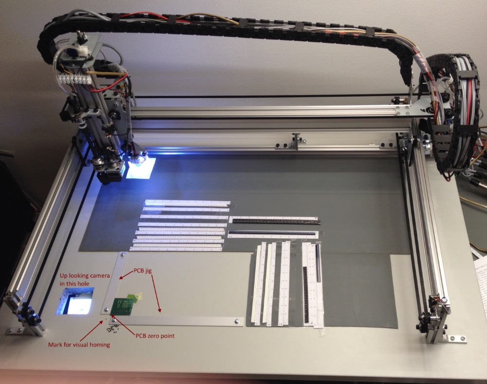
Here is how my table was set up (at the time of the picture, the machine did not yet have automatic nozzle change or the holder) (click for a bigger image):
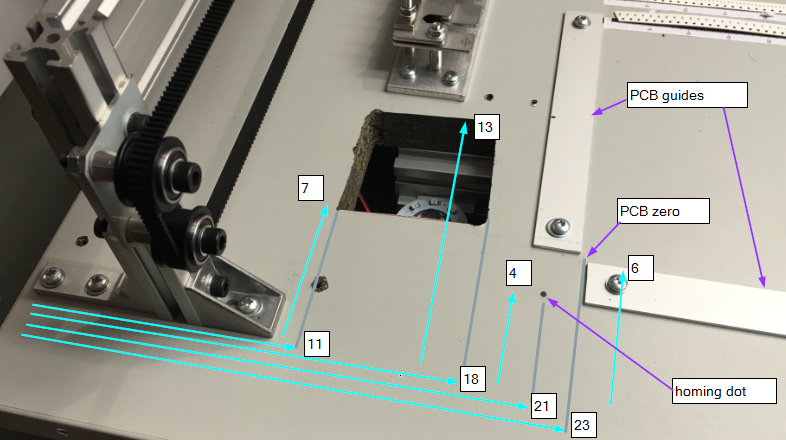
And here is another image, showing my measures (approximately, in cm’s):
Here is what you are going to put in to the hole:
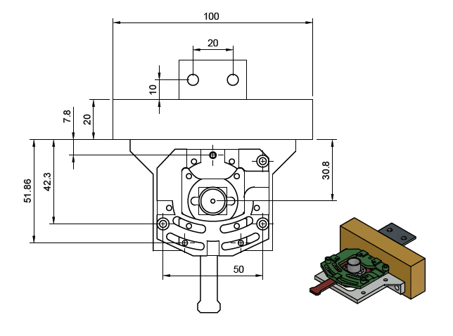
For 1:1 PDF, click here.
The mustard color block is an aluminium bar that is holding the camera assembly, and the dark gray piece with two holes attaches the block to the table. At least some of this block should take support from the underside of the table. You will need access to the holes marked with +, from the top, so make the hole big enough. You also need access to the lever pointing down (towards the front of the table); for that, access from below table is ok. The camera cable is secured to this lever and the cable is somewhat stiff, so you need a few cm more room from the lever tip forward. If your table top has support structures underneath, you need to consider this.
Position the machine on the table. Make sure the gantry and the Y bar moves freely. Take cross measures to make sure the machine is as square as you can make it, while keeping the movement smooth. The smoothness of movement is more important than squareness, since we’ll find-tune the squareness in software later. Don’t skip that step!
Secure the machine to the table or the base using M5 washers (provided) and suitable screws (not provided). Don’t screw the axis support plate (in the middle back of the machine) to the table yet.
You may keep the front extrusion in place, but using the machine is easier with an open front. Once the machine is secured, you can remove the front bar:
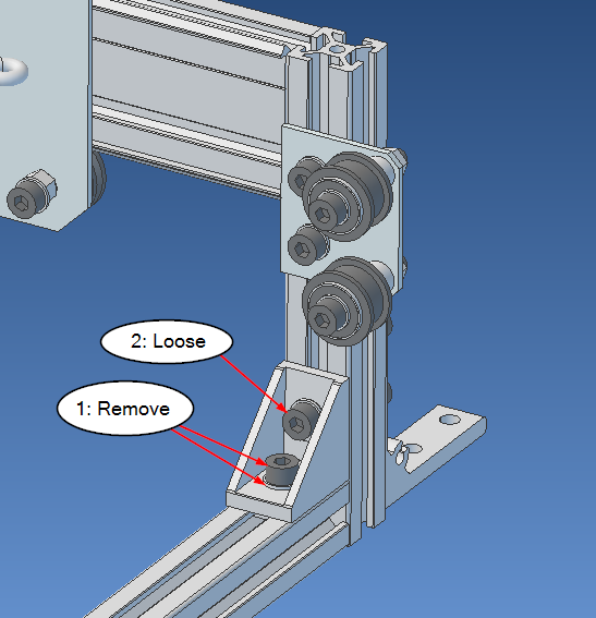
Remove the indicated screw and washer on both sides and loosen the indicated screw. Remove the long extrusion and push the bracket down to the table. Tighten the bracket back to the vertical extrusion and screw the bracket to the table, providing additional support.
Re-check that everything moves smoothly.