This page describes the Nozzles setup page. First, read and understand this page, the actual instructions for setting up the nozzles follow.
The software page looks like this:
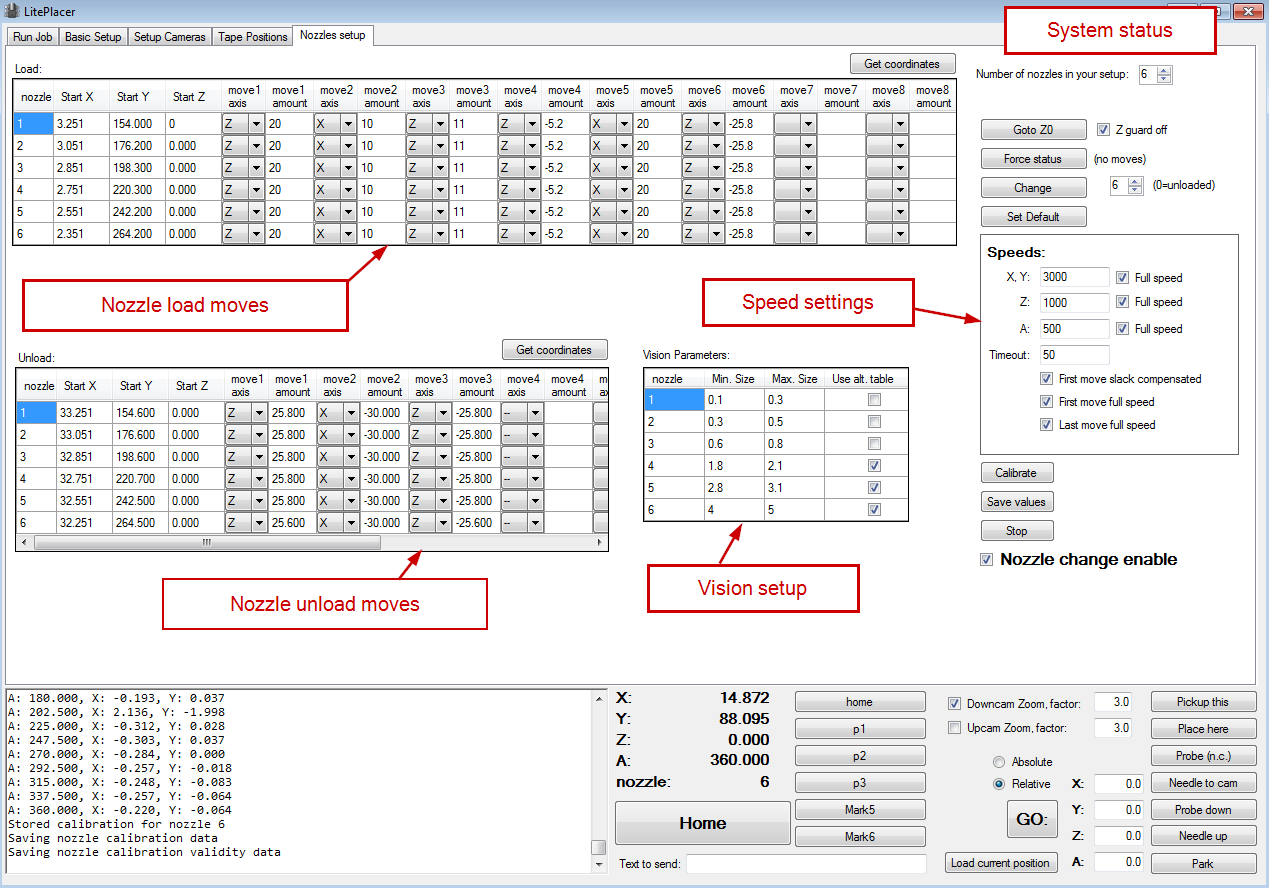
The major areas of the page are labeled above; we’ll go through each below. Non-visible features of the page are that slack compensation is turned off (and restored when you leave the page); we don’t want to do the slack compensation shifts inside the holder! Also, you can jog and move the machine with F keys with the head down; the operations would be impossible to set up otherwise.
Load and unload move tables
You see two tables, one for loading nozzles, another for unloading. For each nozzle, the table has start position for X, Y, and Z coordinates. The A coordinate (rotation value) is automatically set to 0 for the operations. Then follows a series of moves, where you set the axis and value for moves. The above shows my setup: To load a nozzle, the machine takes the empty adapter above a nozzle (start position), lowers the adapter to the nozzle just a little (move 1), takes the nozzle away from the holder end to allow a bit of movement in the loading process (Move 2), pushes the adapter fully in (move 3), releases the adapter spring and lifts the nozzle a little from the holder (move 4), fully removes the attached nozzle from the holder slot (move 5) and finally lifts the head to zero level (move 6). You can see this on the introduction video (https://www.youtube.com/watch?v=3c5Vtuefm7o) at 2:27.
Right clicking the load table gives you two shortcuts: “Goto to start position” moves the machine at the start location of the selected nozzle, as expected. “Copy moves from nozzle 1” fills the table for rest of the nozzles after you have set up the first one; the idea is that only the start location changes, most likely you want each nozzle to be loaded the same.
Right clicking the unload table has more options: “Goto start position”, as above. “Copy unload start positions from load end positions” calculates where the the load sequences end, and puts these coordinates to the start locations of the nozzles. “Get unload moves from load moves” assumes, that the standard LitePlacer holder (ore similar) is used and puts in a s sequence that takes the nozzle to the level where it goes in to the holder slot, moves it where it was picked up and lifts the holder back up (see the screenshot). These are good starting points, but do not take them as is without checking. Please see the nozzle setup instructions page. Finally, there is “Copy moves from nozzle 1” also. Again, you’ll set the moves once for the first nozzle (assuming you are not happy for the guesses made) and can use the same sequence for the rest.
“Get Coordinates” button copies the change from machine real position to a move and advances the selection to next move. To use, you’ll first click a start positon box of the nozzle you are setting up, like you would start to fill out the value manually. Then, you’ll position the nozzle holder to the start position. Most likely, you take it temporarily down to find out the exact location where it would enter the nozzle nicely (see the setup instructions page) and take the head back up. Note the “Goto Z0” button on upper right corner, doing just that. Click the Get coordinates button, and the current location is filled out for you and the next move is selected. Take nozzle down for the first move amount, click the button. The software notices the change, fills out the values and goes to next position. Do the next move and repeat, until finished.
Vision Setup
On the Camera Setup Page, Up Looking Camera tab there are settings for the nozzle image processing. This works much the same as finding circles during the down camera setup. (https://liteplacer.com/camera-setup/). There are two options for the vision operations to use, standard and alternative. The selection is done by the “use alt. functions” checkbox on the nozzles setup page. You can get the nozzle to up camera on the camera setup page by clicking first Up camera / Go there and then Nozzle Down.
For accurate calibration of the nozzles, the vision system needs some help. First, the nozzles have several circular features, and we want the calibration to use the section that actually touches the part. For each nozzle, you set up the maximum and minimum radius accepted for a measurement result. The LitePlacer standard nozzle radiuses are 0.5 / 0.225; 0.75 / 0.4; 1.1 / 0.7; 2.0 / 1.2; 3.1 / 2.0; and 4.5 / 3.75 (outer / inner, in mm’s; diameter double these). Note, that you can set the software to look either the outer ring or the inside hole. When you set up the vision processing for the nozzle tip recognition, the vision setup page has min. and max radius setting as well as maximum distance that is accepted.
You might see several color-coded circles highlighted; the colors are for separating the smallest and closest to center:
– if closest and smallest are the same, it is drawn in magenta (pink)
– if not, smallest is aqua (light blue) and closest is lime (green)
– other circles are drawn in orange
Try to get a reliable recognition of one but only one circle with the given size limits for each nozzle.
System Status
On top right corner, you set up the “Number of nozzles in your setup”. LitePlacer as standard has six, but you can use the software for other setups, too. The tables are automatically resized. When setting up the system, you often need to raise the head to zero position: “Goto z0” does this. “Z guard off” prevents machine moves when the head is down. This is a standard precaution on the software, but you want it off (box checked) on this page.
Then , there is a number box, common for three buttons: “Force status” does no moves, but changes the system status to reflect the real world situation, should these get off for some reason. Do take it a habit that when you power up the machine or after any unexpected situation, you check the loaded nozzle and the software nozzle status (above home button in the lower section). If these don’t match, you can correct the situation here. “Change” changes the nozzle to the nozzle indicated in the selection box. “Set default” makes the indicated nozzle the default nozzle to use.
Speed Settings
You might want the nozzle load and unload operations to happen at slower speed than the machine otherwise uses, and you definitely want to do that during setup! On this box, you can select if the moves are done at full speed and if not, the speed to use. There are separate settings for X and Y, Z and A moves. You can also have the move to the start location (first move) to use slack compensation for best accuracy. The first and last moves can also be done at full speed while the other moves are done slower.
Other settings
The “Calibrate” button measures the offset and wobble for each nozzle and stores the result. My experiments show the repeatability of the nozzles to be excellent; in other words, if you load a nozzle, unload it and use another one and then load the first one again, the first nozzle will sit on the adapter on same location each time, with high accuracy. This allows us to store the calibration and re-use the results, there is no need to repeat the measurement and slow down the operations, which was the case with the first model of LitePlacer. On the other hand, you might find it unnecessary to use calibration at all; you can do that on the run job page. Do your own experiments and performance analysis.
“Save values” button saves the data in the tables. Although the data is saved when closing the program, you might guard yourself and save it right away when you are happy about the setup.
The “Stop” button stops a nozzle change operation.
The “Nozzle change enable” checkbox tells the software to actually use the nozzles in operation.
It is not shown in the above screenshot, but there is a button for troubleshooting, that prints the nozzle calibration data to the log window, not surprisingly labeled “Dump cal. data”.