Currently, the most accurate method for IC placement is to use a jig of some sort. I simply cut a few L shaped stickers and put them on a piece of blank PCB. I push the ICs to the end of the sticker getting the part to a repeatable pick up position. This works until I get a better system; I’m thinking about something with a custom stencil or something like that… Anyway:
To use a set pickup location for an IC, start by adding a new tape in Tape Positions page. The “Edit Tape Parameters” dialog comes up. Check the “Use coordinates directly” checkbox. Note, that the camera image on the main window below gets a grid. Also note, that while the dialog stays topmost, you can activate the main window below, allowing you to jog the machine in position. The grid rotates with the A axis.
Put an IC in your jig, and take the camera over the part. Move the machine and rotate the A axis (the grid rotates, too) until you are happy. Click “Get current” button under the First X and First Y boxes. Set also the Part Pitch to 0; this makes the machine to pick up from the same location each time.
See the image below (click for full size):
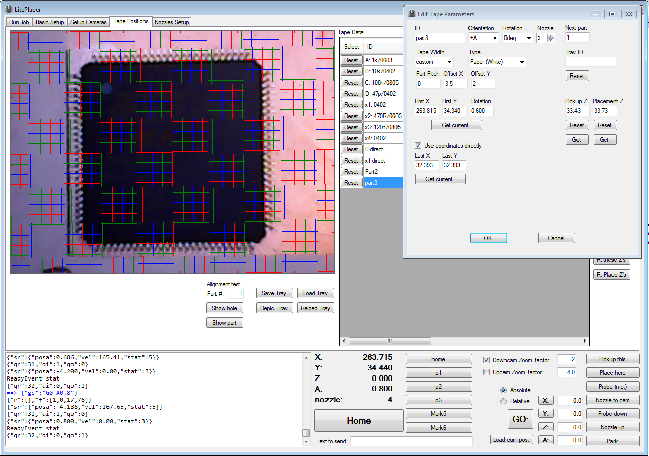
Although the color scheme is subtle, note how the bottom window is active. and how the rotated grid aligns with the part. Part pitch is set to 0. The rotation, orientation and type values on top of the dialog will not be used when picking up the part.
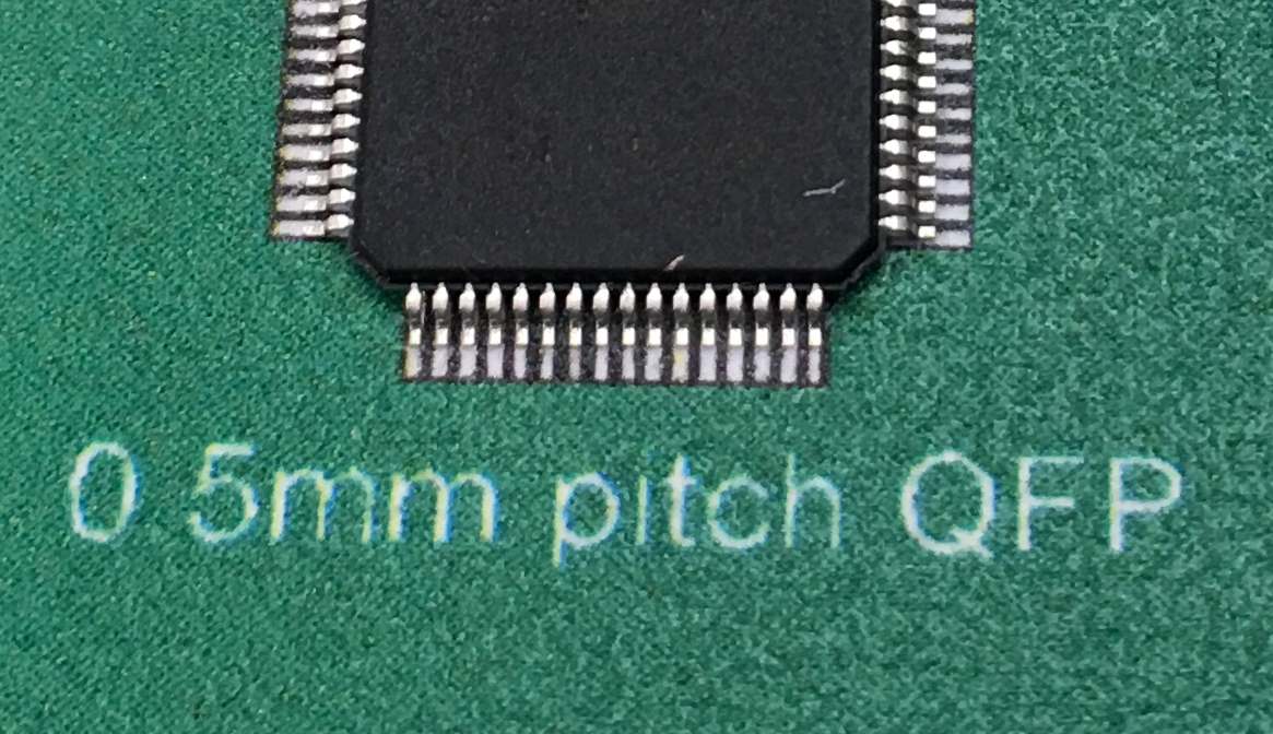
Note, that placing small pitch ICs is close to the capabilities of this simple, economical machine. You need to be precise in your calibration: If the camera offset, up camera location and nozzle calibration are each even 0.1mm off, the combined error of 0.3mm is more than half of pin to pin distance. On the other hand, if you do your calibration carefully, this is possible (actual result).