Please read the description of the nozzle setup page here. For repeatable results, I recommend using a reference for rotation zero. There is no homing on rotation axis, but make a mark on the big pulley so that you can see the axis position. Make it a habit to look at the pulley before powering on the machine, and if the mark is not pointing to your zero location, turn the axis by hand. You don’t need to be super accurate on this. I have a line on the pulley (not on the surface that the switch rests against) that points to me when the axis is at nominal zero.
Also, note that all coordinates in the system are in relation to the optical homing result. If your camera is not set up yet or if you change the camera settings, your start coordinates will not be valid anymore (since the locations of the optical homing mark and nozzle adapter changed in relation to the camera).
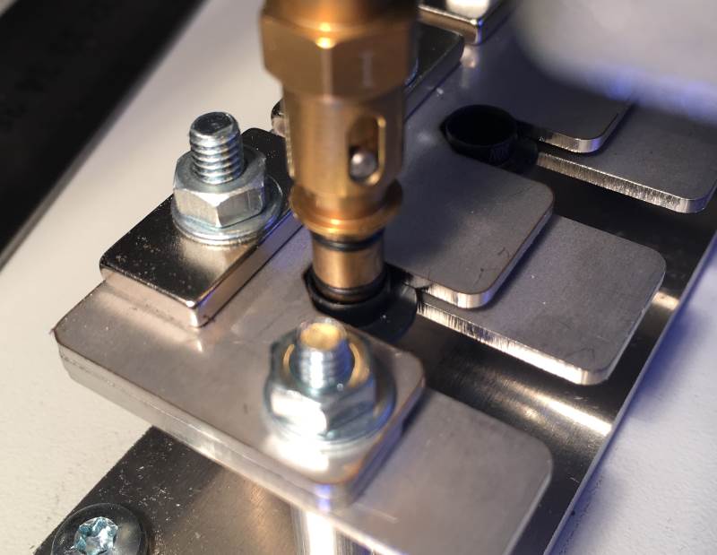
Start by finding your nozzle load start position for nozzle #1 (closest to you). If the rotation is not at 0, make it so. (Sending “G0 A0” from the text box does this, and you can also use the GO button and the location boxes.) If you have a nozzle attached to the adapter, remove it and place to the holder. Jog the adapter down and over the first nozzle so, that it would go in up to the first seal ring without touching the nozzle itself. This image shows what we are aiming for, although the adapter is not quite at the correct position:
Be precise! Click Goto Z0. Click the StartX box on load table on nozzle 1 row, and click get coordinates. The current machine location is copied to start location. Double check by moving a machine a bit, right-click the load table at row 1 and select goto start. Jog the head down and see that the adapter would indeed go to the nozzle without touching. If needed, check “First move slack compensated” checkbox. Repeat if needed.
The nozzle slots are 22mm apart. In theory, you can copy the values adding 22mm to Y for each nozzle. You can also put 22 to the Y box at the bottom of the window, check Relative and click Go. From one start location this should get you to next and is a good starting point. In practice, you will need to do some adjustments; you would be very lucky or good in assembly to have the holder exactly aligned to the machine moves!
Once you have found the start locations, you’ll set up the moves. As noted, I use a sequence that first lowers the adapter to the nozzle just a little, about to level of the first seal (move 1), takes the nozzle away from the holder end to allow a bit of movement in the loading process (Move 2), pushes the adapter fully in (move 3), releases the adapter spring and lifts the nozzle a little from the holder (move 4), fully removes the attached nozzle from the holder slot (move 5) and finally lifts the head to zero level (move 6). This is because I noticed that in my holder, the nozzles lean a bit to the groove end and my Z axis is not going down exactly vertical (I need to do something for that…). Therefore, there was some resistance from the track ends, and I decided for the more complex operation.
You might find a simpler sequence sufficient. In any case, here are some issues to consider:
The slot and the nozzle header is a tight fit, on purpose. (The adapter needs to go in straight. The magnets are needed for holding the nozzles in place even if the machine could be shaking a bit, but in a looser slot, they would pull the nozzle to an angle.) Therefore, it might be difficult to see if the nozzle is at a right height in relation to the holder. Using a piece of paper as a gauge helps: If you can put a paper between the holder and the nozzle on both over and under the nozzle “shoulder”, you can move the nozzle freely in the slot.
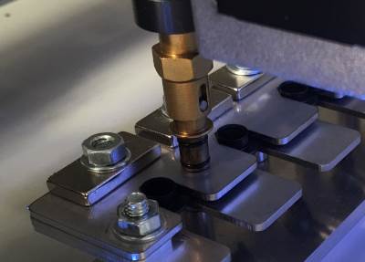
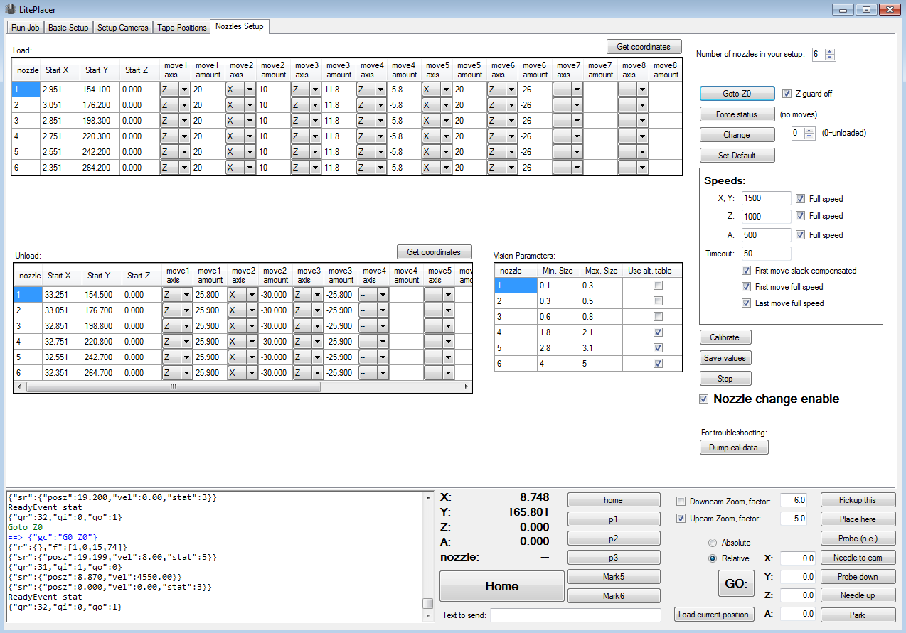
The screenshot below has my current settings. Your Z levels and starting positions will be different, but you can get a reference: Jog the nozzle adapter carefully to the top of the holder and put a piece of paper between the adapter and the holder. This image shows the idea, without the paper:
Jog down carefully and note, when the adapter starts to grab the paper. Note your Z level. When I do this experiment, I get 19.2. For example: if you get 19.7, your machine needs to move 0.5 more to get the nozzle to the same level. If you want to copy my moves, you need to add 0.5 for a correction.
Also, when unloading the nozzles I found the nozzle to touch slightly the holder groove edge when using automatically calculated unload moves; I needed to trim the unload start positions Y dimension slightly.
Here is screenshot from my current setup (click for a larger image):
Do run the load/unload sequence manually a couple of times to be sure about the moves before trying it automatically. Do use slow values and have your hand on your reset button (you do have one, don’t you?), just in case.
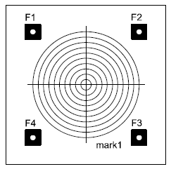
The nozzles should run very true, with almost no or no wobble. You can check the “Don’t use needle correction” on the run job page, and the software does not use any calibration values. If you do want to use calibration, note my vision parameters table content. The nozzles have many round features, and we want to use the part that touches the components, not some other round thing that might be visible. The size limits allow you to do that. The LitePlacer standard nozzle diameters are:
#1: 0.5 / 1.0
#2: 0.8 / 1.5
#3: 1.4 / 2.2
#4: 2.4 / 4.0
#5: 4.0 / 6.2
#6: 7.5 / 9.0
(outer / inner, in mm’s).
Use the calibrate button only after you are happy with the nozzle change. The calibrate button will change to each nozzle in turn, take it to the camera and run calibration. Therefore, the nozzle load/unload needs to work smoothly.
The repeatability of the nozzles is excellent; in other words, if you load a nozzle, unload it and use another one and then load the first one again, the first nozzle will sit on the adapter on same location each time, with high accuracy. Therefore, the software stores the calibration and re-uses the results. Therefore, you only need to succeed on the calibration once per nozzle. On the other hand, you might find it unnecessary to use calibration at all; you can do that on the run job page. Do your own experiments and performance analysis.
Do test your machine and your nozzles to familiarize yourself with the performance and to correct any issues. Note, that there are a few test buttons in the low right that can help: Needle to cam uses correction (if enabled) and takes the machine over the up looking camera, so that clicking needle down on the camera setup page should result the nozzle to be located in the center. Probe (n.c.) button takes the nozzle down to the spot seen in the down looking camera. Probe down does the same, using correction.
To assist in performance evaluation and setting up, I prepared a super simple PCB:
The pdf and csv are here.