Please note, that the limit switches should be operational at this point, before going further!
Also, now is an excellent moment to re-check the tube movement: I recommend that for setup, you loosen the springs and use the weight of the tube as a starting point. When you push the tube up from the nozzle tip, these should happen, in this order: The tube goes up, triggering the switch. Then, the bottom collar goes up against the lower bearing. Only after this, would the spring in the nozzle adapter start to compress. When you let go, the tube should drop fully down under its own weight, at all rotational positions. If this is not the case, fix it, as the next steps will mask the error, which is later hard to diagnose.
If you haven’t done so yet, attach a nozzle to the pickup tube. If you triggered the switch at this or the previous chapter, press reset on the TinyG and after the message, click “Clear error” to re-establish connection.
On the Basic Setup tab, Nozzle height box, put 0.2 to Switch hysteresis box as a starting value. Then, click calibrate, and follow the instructions. First, you should place a regular height PCB under the nozzle; you can jog the machine to a suitable position for this. Clicking next will take the nozzle down until the switch triggers, This is the full Z0 to PCB surface measurement.
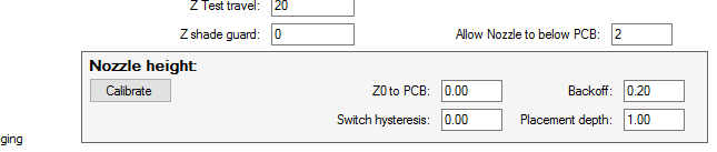
Then, you are asked to jog the nozzle up until it just touches the PCB. Pressing F11 will take the nozzle up 0.1mm at a time, Shift+F11 is 1mm up. Do not try to move the machine in XY direction during this! It is sufficient accuracy to take the nozzle up until you see that it is not touching anymore, then one F12 press, 0.1mm down. This establishes the nozzle backoff value. If the backoff value turns out to be significantly less than 1mm or so (2mm recommended), adjust the Z Max switch (the limit switch resting against the gear) and do this again.
The placement depth is the value down from backoff height, that is used for placement operations. For now, set it half of backoff. Note, that this value controls both the pickup/placement force as well as guards against false triggers.
The meaning of the values
Z0 to PCB: Nominal value from Z0 (Z axis fully up) to the nozzle tip PCB surface.
Switch hysteresis: Value from the switch trigger point to real measurement value. When the head is moving down and the switch triggers, it takes some amount of travel for the head to really stop, because of limited acceleration. 0.2 to 0.5 is a good starting value.
Backoff: How much the head needs to go up from full down (switch triggered position, full down force used) to barely touching (zero down force). This is adjusted by trimming the switch angle.
Placement depth: When picking up and placing components, the head goes down this much from the barely touching level. You should use some down force when pushing parts to the paste, so this value needs to be more than 0. You also want the limit switch to be on to guard against accidents or unforeseen situations. However, you don’t want false triggers, so you should not have placement depth too close to backoff value. For example, if your backoff is 1mm, placement depth of 0.9mm leaves only 0.1mm between normal operation and the guard switch triggering. This is way too little, you will likely have more combined variance from the table, PCB and the assembly .