Connecting to Camera
Select the Setup Cameras tab on the program. It looks like this:
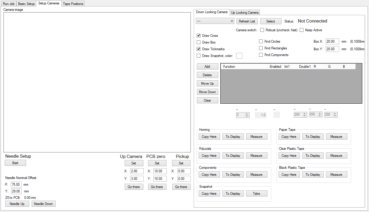
To the right of the image box, notice the camera selection section:
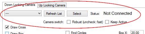
The leftmost selection box lists your cameras. If not, press the “Refresh List” button. If no cameras appear, check your connections. Select one of the generic USB cameras, until you get the image of the down looking camera to appear. Now is also a good point to check that you can get an image from both cameras. If you have troubles connecting to the cameras or switching between them, please see troubleshooting section at the end of the next page. Note, that installing any software is not required, although there is a disc inside the camera boxes.
Loosen the camera attachment screw so, that you can turn the camera, but the camera does not fall. Adjust the camera to approximately in right orientation.
Zoom
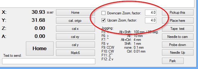
At the lower right of the program screen, there is a selection box for camera zoom on/off and for the zoom factor. Make yourself familiar with this function, it will be helpful in adjustments:
Adjust Diffusers
The cameras have built-in lights, that normally do more harm than good. the intensity control for the built-in lights is in the USB connector. Turn these down.
Adjust the shades so, that you get evenly diffused light on your image. It is not overly critical, but you still want good, even light to your system. Here Is an example of bad and an on OK light setup:
Align the Camera
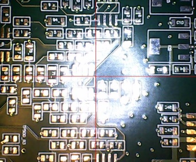
Select the “Draw Cross” tick box on the right of the image; this draws the red alignment cross on the image. Put a ruler on your table, and adjust the position or jog the machine so, that at the center of the image, a point on the edge of the ruler aligns with the cross. (Hint: At this point, you might put a needle to your table and support that point of the ruler against it.) Move the machine in left-right direction to the other end of the ruler. Adjust the ruler so, that at both ends, the ruler edge aligns with the center cross. Your ruler now aligns exactly to the machine X axis. Adjust the camera so, that the horizontal red line matches the ruler edge. Tighten and re-check that the alignment is good.
Set the Camera Units
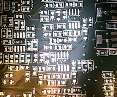
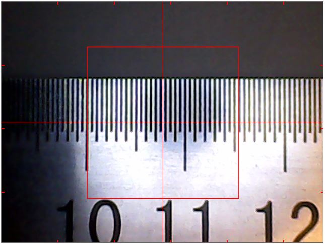
Check the “Draw Box” tick box and adjust zoom to less than 2, so that the box fits the image. Put a ruler under the camera and measure the box size, like this:
Put the true size of the box (here I put in 15.4mm) to “Box X” and “Box Y”. (There shouldn’t be a big difference in X and Y, if any.) Your machine now knows the size of things it is looking at.
Additional Ways to Move the Machine
When there is an active image on screen, you may move the machine to particular spot by clicking on the image; the machine moves to that spot, making it the image center. Also, by Ctrl+click, the machine takes the image box to represent your work area and moves to the point you clicked. By selecting the “Draw Tickmarks” tickbox, you can draw marks on side of your image representing 100mm intervals on your work area (set “on” at above). Having same marks drawn on your table makes it easy to aim with this function.
Make a Homing Mark
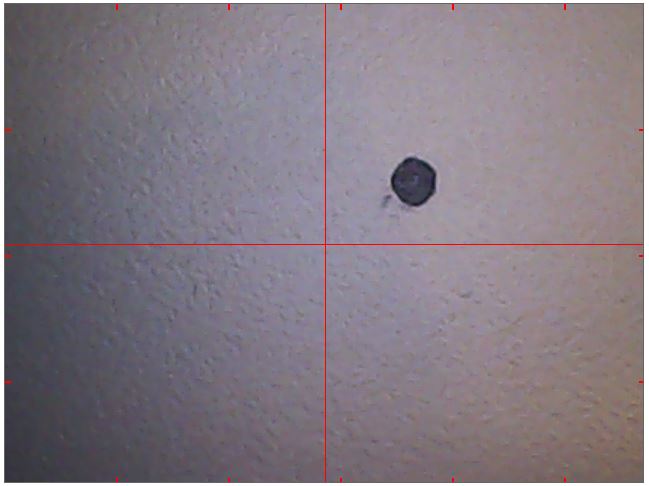
Go back to Basic Setup tab, and click “Home XYZ” button. When the homing operation finishes, come back to Camera Setup tab, and make a mark in a position up and right, less than 20mm from the image center. The mark should be smallish, clearly visible circle. Here is mine, it doesn’t need to be perfect 🙂 :
Setting Image Processing Functions
On the right of the image, there is a table (empty at the moment) and some buttons. This table enables you to select and configure various video processing functions and see what the measurement algorithms see.
You can read descriptions of all algorithms in the reference section on this site (TBD). For now, you should make an effort to stay with the simple basic ones: “Measurement Zoom” enlarges the center section of the image for further processing, making small features easier to measure; “Grayscale” removes color; “Invert” makes black to white and vice versa and “Threshold”, which makes image pure black and white.
Clicking “Add” inserts an empty slot to the table. You can select a processing function on the leftmost column, and turn it on and off on the enable tick mark. If a function has any parameters to set, clicking the function puts adjustable parameter(s) of a function to the box(es) below the table. By Up and Down buttons you can move selected algorithm position in the queue, Delete removes it from the table and Clear removes all processing form the image.
Finding Circles
Many functions of the machine is based on finding circles with the video processing. The circle finding algorithm looks for a white circle on black background close to the image center. When you select the “Find Circles” tickbox, the system highlights any circles it finds on the image. For example, here are my settings for recognizing the homing mark above:
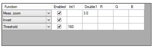
The Zoom makes the mark a bit bigger for recognition, but is not absolutely necessary here (but doesn’t hurt either). The mark is black on grey background, so Invert comes next, making it light gray on dark grey. Finally, Threshold converts the image pure black and white, which is what the circle finding algorithm needs.
You might see several color-coded circles highlighted; the colors are for separating the smallest and closest to center:
– if closest and smallest are the same, it is drawn in magenta (pink)
– if not, smallest is aqua (light blue) and closest is lime (green)
– other circles are drawn in orange
Find a combination of algorithms that gives reliable result for your homing mark. Experiment with the threshold value; for reliable operation, you should have a comfortable range where the recognition works. The bigger the better, but aim for a range of 40 or larger. This should be easy to achieve. Set the threshold value to middle of the range.
Setting and Retrieving Measurement Functions
As you notice, there are six boxes below the algorithm table: Homing, Fiducials, Components, Paper Tape, Clear Plastic Tape and Black Plastic Tape; each with “Copy Here”, “To Display” and “Measure” buttons.
Each of these boxes hold a non-visible copy of video processing functions table. By pressing “Copy Here”, the functions currently in the visible algorithms table are copied to the box. “To Display” performs the copy to other direction, making the algorithms visible and adjustable. Now, when you have set the homing mark algorithms, press the “Copy Here” button of the Homing box. You can clear the algorithm table by pressing Clear and verify, that you can them back with the “To Display” button. Now, press “Measure” button. The system does one measurement for circles and shows the result in the log window on the low left. You’ll see a list of used video processing functions and something like “X: 4.500, Y:3.211”. This means that the circle is 4.5mm to right and 3.211mm to back from the point the camera is looking at.
About Fiducials
The PCB needs alignment marks, called fiducials. For details. please see https://liteplacer.com/pcb-requirements/. The standard fiducial is a round dot with good clearance, but there are features that help using other types of fiducials or board features (vias or pads) as alignment marks. The “Fiducials” box sets the parameters for these.
True Homing
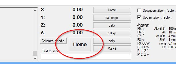
When the homing mark recognition works, press the big Home button on low center of the window.
The machine will first run the mechanical homing function, which by now, you are familiar with. Then, it uses the video processing you just set up to get itself precisely on top of the homing mark. Please note, that the coordinates are not set exactly to 0, but to the result of last measurement correction. The process is typically repeatable to 0.02mm (!) or so.
Make it your habit to press the Home button every time you start the program or power to motors is switched off.
IMPORTANT: Homing on rotation axis
There is no automatic homing on rotation axis. Therefore, make a mark to the big pulley, and make it also your habit to manually check that it points to the same direction (to front, for example) before you turn power on. This is important for the nozzle calibration to work properly.