The only thing left in setup is the image processing for down looking camera. Go to the camera setup page again. You have already set the video processing functions for homing mark recognition. (For a refresh on how to use the processing boxes, please see the Downlooking Camera Setup page.)
All the video processing functions except component recognition are looking for a white circle on a black background. The threshold function makes the image pure black and white, and should be the last in the chain. Add functions to the table and arrange and tune the parameters so, that you get reliable recognition with reasonable large threshold tolerance.
Fiducials are location marks that should be on your PCB. The industry standard fiducial (according to IPC-7351) is a 1mm diameter round dot. There should be a 2mm solder mask opening and no circuitry or markings within this feature.
The three tape function boxes are for the three commonly used tape types. As noted, the machine is looking for the tape holes.
Loose component pickup
For loose component pickup, the machine needs to see a single component. To set up for this, place a component to the pickup spot (set up already at Special Positions page, assuming you are following these instructions linearily). Jog the machine there, uncheck other “Find” boxes but set the “Find Components” box. You will (eventually) see something like this:
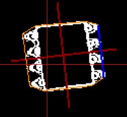
The orange lines show the outline of the component and the dark red lines show the center point and rotation of the part. Try to get the image as stable as possible, although with current software, it won’t be rock solid. Note also, that some functions are processing-heavy: You’ll notice the video frame rate dropping and image lagging real time. Avid using these if you can.
My Settings
For reference, here are my settings. As shown in some pictures, my table top is darkish grey:
Homing:
- Zoom: 2
- Invert
- Threshold: 160
Fiducials:
- Zoom: 3
- Threshold: 60
Components:
- Edge detection: 1
- Threshold: 200
Paper tape:
- Zoom: 3
- Invert
- Threshold: 90
Clear Plastic tape:
- Zoom: 3
- Invert
- Threshold: 140
Black Plastic Tape:
- Zoom: 3
- Threshold: 80
For the black tape, I extend the white ruler sticker under the holes; dark grey table top shadowed by the black tape doesn’t give very much usable contrast.
When writing this I noticed that on most of the videos and accuracy description images, I haven’t actually used the zoom functions(!). Doh. I might have in fact achieved even better results, but I am not re-shooting those. Lets just say that I am very convinced that the results shown will be generally achievable.
Congratulations! Your machine is now built and set up and ready for test runs. It is a very good idea to do what I did: Make some laser printed images of circuit boards and attach them to black pieces of PCB. Your office store will have Post-It glue or equivalent in a spray can: This is recommended, it makes easy to attach the printouts to the blanks and make the prints somewhat sticky, simulating the stickiness of real solder paste.
Do enough test runs to familiarize yourself to the functions and operations of the machine and the software. For instructions, please see the Using the Machine section.
Good luck and have fun!