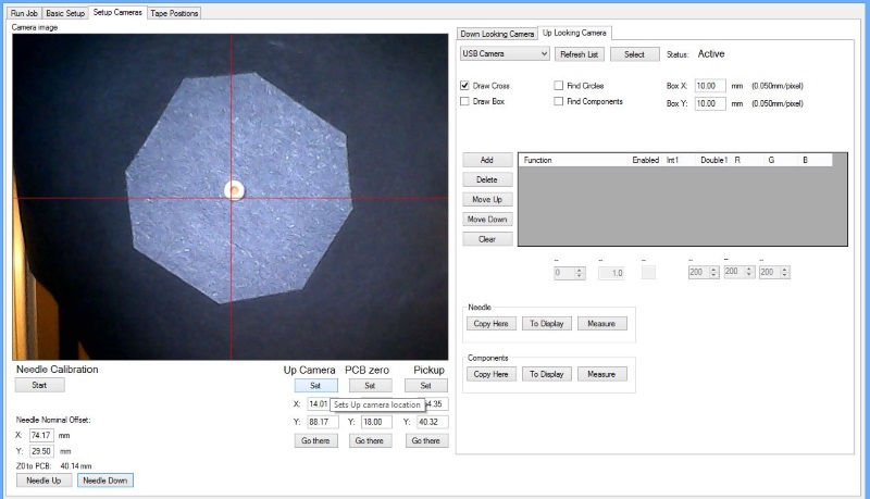
Next, we set up the video processing for the needle calibration subsystem. First, home the machine (click “Home” at the bottom section). Select the “Setup Cameras” page, and on there, select the “Up Looking Camera” tab and click “Select”, so that you have the Up looking camera image on the image box. Take the machine to up camera nominal location by clicking “Go there” button at the “Up Camera” group. Click “Needle Down”. You should now have a close-up image of the needle on the screen:
Add “Meas. Zoom” and “Threshold” to the processing functions table and check the “Find Circles” box. Adjust the processing function values (click the number, adjust at the boxes below the table), until you get a robust needle tip recognition:
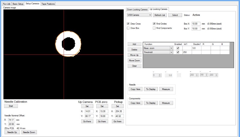
For reference, my values are zoom= 5.0, threshold= 250. You are likely to end up using a largish value for threshold, as the camera is looking at shiny steel tip. Check the processing with a couple of needles and save the settings by pressing “Copy Here” at the Needle box.
Note about needle Measurement, Principle of Operation
Measuring the needle is crucial for correct operation of the machine. The needle tip will wobble somewhat when it rotates, enough to make placement results unusable. The software has a built-in needle wobble measurement routine, which is activated when needed. You can also activate it manually using “Measure Needle” button on the Run Job page.
The basic idea is this: First, you set the location difference (offset) of the needle tip and the down looking camera, in the Needle setup step. If the needles would be perfect having no wobble and the machine perfectly built so that the pickup tube does not shift when rotated, this offset would be sufficient for operation. But it is not so, the needle and the tube wobble somewhat when rotated. Therefore, the offset is only nominal; when you rotate or change needle, the tip position changes. The needle measurement routine measures this change, in several rotation values. The software uses the nominal offset plus the measured difference to figure out the true needle tip position.
There are some diagnostics to make sure needle calibration is done accurately and works as intended. On Low right corner, there is a test button labeled “Probe (n.c.)”; the n.c. stands for No Correction. This will bring the needle down without applying any correction. The button “Needle to cam” will take the needle to uplooking camera position, using needle calibration. Clicking this and taking the needle down should take the needle tip precisely on center of up camera image. The button “Probe down” will take the needle down to exactly to downlooking camera image center.
Experiment with these, until you get a reliable needle calibration and precise results (hopefully without needing to recalibrate the needle offset).