Casing
Casing for the electronics is totally optional. I mounted the electronics and the power supply on an aluminium plate and had XLR connectors for the wires. The connector choice is an overkill, but I’m an audio guy, so I had plenty of those around. 🙂 Anyway, it is a good idea to have some connectors; connecting wires directly to the TinyG board would put unnecessary stress on the board. Here is a picture of my setup; I’m sure you can come up with something nicer:
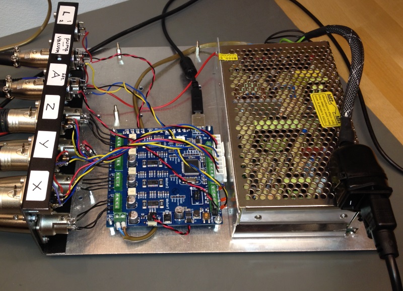
For reference, the bottom plate is 30cm x 25cm.
About Cable Management
When you install cabling, pay attention to moving parts of the machine. If the machine movement twists cables from connection or solder joints, the connection will eventually fail. Do attach the cables to the machine so, that movements bend the cables from the insulated sections.
For general routing of the cables, see this page. For a neat way to do cable connections, please see here.
Wiring diagram
The one-page wiring diagram is here. The page doesn’t render correctly on all browsers; if not, download it. Do read the rest of this page and the subpages as well anyway.
TinyG Connections
CAUTION: Before first power on, turn motor current trim pots to a low position. This is especially important on A axis. Start with 10% setting on A.
Counter-clockwise decreases current, so I’m asking you to first turn A axis potentiometer fully counter-clockwise, then clockwise a little. TinyG connection diagram is here. For first setup, start with a low setting on motor current trim pots. This is especially important on A axis. (For reference, I ended up with these motor current settings, for no particular reason: x: 100%; y: 90%, z: 60%; a: 20%.)
Motors
See the Wiring the Motors page.
Limit Switches
Visit the Wiring Limit Switches page.
Pump and Solenoid Valve
The pump and the vacuum solenoid valve are controlled by FET switches. See this page.
LED Ring Lamps
See the TinyG connection diagram. The ring lamps run at 12V. Configure the fan output to 12V, and wire the ring lights to the fan output. If you don’t have the right connector for the fan output (I didn’t), don’t worry: A regular female pin header connector works fine. Alternatively, you could wire the lights in series connection and connect them directly to the 24V supply.
Power Supply
Use a 24V power supply, at least 5 to 6 amps. This should cost less than $50. I like MeanWell supplies, such as NES150-24 or S-150-24, but about any similar supply should be fine.
Safety Switch
Last but not least, have a kill switch! This is a moving machine, and safety is important. Besides, during testing you might crash the machine, so you want an easy way to cut power to the motors. Wire the switch to the reset line of TinyG (see the one-page wiring diagram here, emerengy stop middle right). I used the Adafruit big red button (mounted on a plastic container):
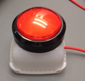
The reset on TinyG deactivates the motors, and this has been sufficient for me. In your country, it might be required to have a switch that actually cuts the power.
Wiring for OpenPnP software
The OpenPnP software has Z axis polarity inverted from LitePlacer. If you plan to use OpenPnP only, wire Zmax limit switch to Zmin input and vice versa. Swap also one pair of Z motor coils. If you plan to use both of the available software packages, install a switch that does the above.
Next: Setup and Calibration
Continue here.