I'm interested in your kit, and have questions on the software:
it seems to me that a pick and place isn't very valuable until you add a lot of image processing and recognition routines. It is unclear to me based on your website about how much you've been able to implement with regards to your downward and upward looking cameras.
these cameras and their software are the most important aspect of a pick and place. the software needs to be able to:
1.) accept a set of part center coordinates from a CAM file from eagle, or whatever pcb tool you use - this file will be slightly wrong in x,y, and rotation
2.) use the downward looking camera to go through and manually update / calibrate the real positions that you tell the software, based on what you see on the camera for both the part pickup location, and the part placing location on the board; the software would then do all the coordinate transforms necessary to be able to continue (x,y, rotation, etc.?)
2a.) you only need to do this one time for each job that you're gonna run
3.) the upward looking camera must be able to correct for part rotation, and center location for anything from a 0805, to a tssop micro, to a bga part. right now I see that you have an upward looking camera, but your site or videos don't really show it doing these corrections.
right now, in your video, I see a machine that places parts at an x, y coordinate based on the cam file, but I didn't see you calibrate each location, and I didn't see the machine verifying and correcting x,y, and rotation for parts using the upward looking camera
how far along are you on these software capabilities? maybe I just missed a section of the site explaning that these features are working quite well already.
an x, y gantry machine is one thing, but the software to drive a proper pick and place is really where the need is at to take it from a hobby level machine, to a real contender.
i'm interested in buying a kit, but am skeptical at this time, not having seen clear and confident presentations of the above camera / software capabilities - can you show us what's possible?
Automated rotation correction
Re: Automated rotation correction
Please note that point 2 is done automatically, no manual step is involved. You can see this happening in the introduction video at 1:50, takes a few seconds. The way this works is that there are ficucial marks on the PCB (please see http://www.liteplacer.com/pcb-requirements/). The machine will use optical recognition for the marks, measure their position and calculate the component positions from these. This corrects for board displacement and rotation (1), board scale errors (2), squareness errors (3) and shear errors (4).
1: Board not accurately placed to where the machine thinks it is; significant always
2: Board x-mm and y-mm being different from machine mm's; significant on big boards and home made boards (laser printers are not dimensionally accurate)
3: Squares being slightly diamonds; usually not significant (but corrected anyway)
4: A square being narrow on one side; usually not significant (but corrected anyway)
The parts are picked up from tapes using vision to locate the tape holes (which tells the nominal part position in the tape pocket). There is no further correction on this, nor it is required. Although the parts are slightly misplaced in their (loose) pockets and there is some placement error due to the machine itself, the parts re-align themselves during reflow due to surface tension of molten solder. The errors from placement are smaller than this re-alignment. The machine is good not only for 0805s but 0603s and 0402s, too.
The area which needs and will get improvement is loose part placement. At the moment, the down-looking camera can find a part placed at a manual pickup area, find its position and rotation and place it. Please see http://www.liteplacer.com/running-a-job/, second to last picture. What the machine sees internally is shown in this image:
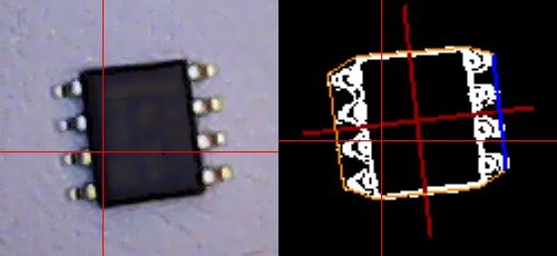
The accuracy of this is good for SOICs but not good enough for 0.5mm pitch or smaller parts. However, this is a prototype builders machine, and I don't consider it a big shortcoming if some operator assistance is needed for these - after all, a typical board will have relatively few small-pitch parts where user involvement would be necessary. Please see http://www.liteplacer.com/phpBB/viewtopic.php?f=12&t=15 for deeper discussion about what I will add to the system next.
1: Board not accurately placed to where the machine thinks it is; significant always
2: Board x-mm and y-mm being different from machine mm's; significant on big boards and home made boards (laser printers are not dimensionally accurate)
3: Squares being slightly diamonds; usually not significant (but corrected anyway)
4: A square being narrow on one side; usually not significant (but corrected anyway)
The parts are picked up from tapes using vision to locate the tape holes (which tells the nominal part position in the tape pocket). There is no further correction on this, nor it is required. Although the parts are slightly misplaced in their (loose) pockets and there is some placement error due to the machine itself, the parts re-align themselves during reflow due to surface tension of molten solder. The errors from placement are smaller than this re-alignment. The machine is good not only for 0805s but 0603s and 0402s, too.
The area which needs and will get improvement is loose part placement. At the moment, the down-looking camera can find a part placed at a manual pickup area, find its position and rotation and place it. Please see http://www.liteplacer.com/running-a-job/, second to last picture. What the machine sees internally is shown in this image:
The accuracy of this is good for SOICs but not good enough for 0.5mm pitch or smaller parts. However, this is a prototype builders machine, and I don't consider it a big shortcoming if some operator assistance is needed for these - after all, a typical board will have relatively few small-pitch parts where user involvement would be necessary. Please see http://www.liteplacer.com/phpBB/viewtopic.php?f=12&t=15 for deeper discussion about what I will add to the system next.